Asus P5WDG2-WS: Intel 975X goes to Work
by Gary Key on December 6, 2005 12:05 AM EST- Posted in
- Motherboards
ASUS P5WDG2-WS: Features
The Intel SATA II ports are conveniently located below the ICH7R chipset and above the primary IDE connector. The SATA II ports feature the new clamp and latch design. Asus did not include the new cable designs in their accessory kit, which greatly enhance the security of the SATA connections. However, the Intel SATA II ports are color coded for primary (Red) and secondary (Black) operation when the ports are set to Standard IDE mode.
The Intel 6702PXH chipset is located in between the DIMM module slots and ICH7R chipset. Below the 6702PXH chipset is a 6-pin jumper switch that allows you to set the PCI-X speed settings to Auto, Force 133MHz, and Force 100MHz.
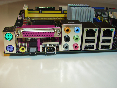
The Marvell 88SE6141 SATA II Raid ports, Intel USB connector, IEEE1394a connector, chassis panel, and Com1 serial port are located along the left edge of the board. The CMOS reset is a traditional jumper design located in-between the BIOS chip and the chassis panel.
We did not have any issues installing an ATI X850 Crossfire Edition setup in the two x16 PCI Express slots. This configuration will render the first PCI-X slot useless. There were not any issues utilizing this slot with video cards containing single slot cooling systems when utilizing our Areca ARC-1110 SATA II RAID host adapter.
One of the main design features that Asus engineered into this board is an exclusive 8-phase voltage regulator power design that can significantly lower operating temperatures while reducing input ripple current and output ripple voltages . In fact, the input ripple current is over three times lower than a traditional 4-phase design while output ripple voltages are four times lower. The power consumption compared to the 4-phase design is about 10% less while the 8-phase design has the advantage of quicker transient responses and increased dependability due to lower thermal values.
The Northbridge, Southbridge, and PCI-X chipsets are passively cooled with heatsinks that do not interfere with any installed peripherals. In fact, this system kept the chipsets cool enough that additional chipset voltage was not a factor in our overclocking tests. Asus places the eight-pin 12V auxiliary power connector at the top of the CPU socket area, but out of the way of most aftermarket cooling solutions.
The BIOS options are abundant on the Asus P5WDG2-WS, with memory voltage to 2.3V, and an extensive range of chipset, bus, and vCore voltage adjustments. Memory ratios are limited compared to the nForce4 Intel Edition boards, but Asus did manage to offer enough settings to make the board competitive. The board fully supports manual memory timing adjustments or allows for an Auto setting that will set the memory to the SPD settings. You have the ability to overclock the system utilizing the AI Overclock profiles that have preset percentages or to use the AI N.O.S. feature that will dynamically overclock the system based upon system loads.
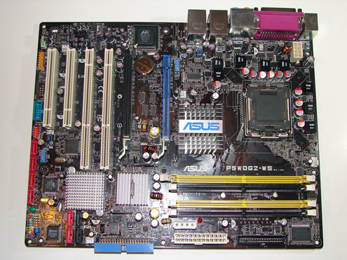
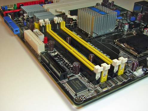
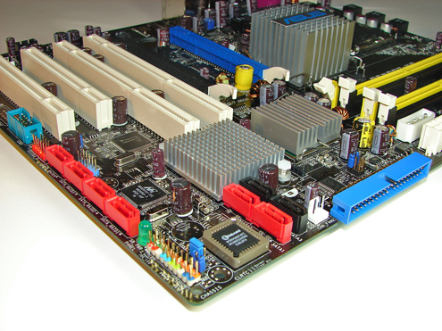
The Intel SATA II ports are conveniently located below the ICH7R chipset and above the primary IDE connector. The SATA II ports feature the new clamp and latch design. Asus did not include the new cable designs in their accessory kit, which greatly enhance the security of the SATA connections. However, the Intel SATA II ports are color coded for primary (Red) and secondary (Black) operation when the ports are set to Standard IDE mode.
The Intel 6702PXH chipset is located in between the DIMM module slots and ICH7R chipset. Below the 6702PXH chipset is a 6-pin jumper switch that allows you to set the PCI-X speed settings to Auto, Force 133MHz, and Force 100MHz.
The Marvell 88SE6141 SATA II Raid ports, Intel USB connector, IEEE1394a connector, chassis panel, and Com1 serial port are located along the left edge of the board. The CMOS reset is a traditional jumper design located in-between the BIOS chip and the chassis panel.
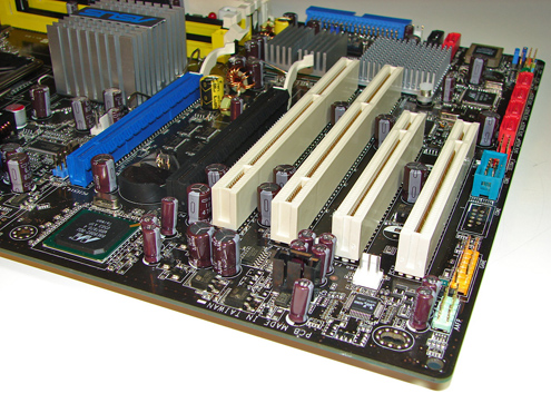
We did not have any issues installing an ATI X850 Crossfire Edition setup in the two x16 PCI Express slots. This configuration will render the first PCI-X slot useless. There were not any issues utilizing this slot with video cards containing single slot cooling systems when utilizing our Areca ARC-1110 SATA II RAID host adapter.
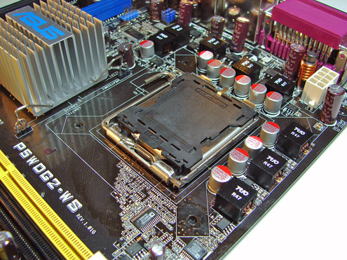
One of the main design features that Asus engineered into this board is an exclusive 8-phase voltage regulator power design that can significantly lower operating temperatures while reducing input ripple current and output ripple voltages . In fact, the input ripple current is over three times lower than a traditional 4-phase design while output ripple voltages are four times lower. The power consumption compared to the 4-phase design is about 10% less while the 8-phase design has the advantage of quicker transient responses and increased dependability due to lower thermal values.
The Northbridge, Southbridge, and PCI-X chipsets are passively cooled with heatsinks that do not interfere with any installed peripherals. In fact, this system kept the chipsets cool enough that additional chipset voltage was not a factor in our overclocking tests. Asus places the eight-pin 12V auxiliary power connector at the top of the CPU socket area, but out of the way of most aftermarket cooling solutions.
The BIOS options are abundant on the Asus P5WDG2-WS, with memory voltage to 2.3V, and an extensive range of chipset, bus, and vCore voltage adjustments. Memory ratios are limited compared to the nForce4 Intel Edition boards, but Asus did manage to offer enough settings to make the board competitive. The board fully supports manual memory timing adjustments or allows for an Auto setting that will set the memory to the SPD settings. You have the ability to overclock the system utilizing the AI Overclock profiles that have preset percentages or to use the AI N.O.S. feature that will dynamically overclock the system based upon system loads.


31 Comments
View All Comments
Tujan - Wednesday, December 7, 2005 - link
Can you tell us what power supply was used on this Asus multi-layered board ? What kind of power muscle did get used. ? [ ]Thanks.Didn't see it right off in table of 'Setup.
Gary Key - Wednesday, December 7, 2005 - link
We used the OCZ Power Stream 520. It is our standard power supply for testing. I have listed in the overclocking setup but not in the regular test setup. I will add that line in the next article.Thank you.
Kensei - Tuesday, December 6, 2005 - link
Cool quote from the man often referred to as the first US psychologist. The psychology building at Harvard, where he was a professor, is also named after him. And I'm pretty sure he got that honor without giving them a ton of money.Kensei
Saist - Tuesday, December 6, 2005 - link
just wondering how the board would compare using the Via Envy HT-S sound chip...Gary Key - Tuesday, December 6, 2005 - link
Would a Chaintech AV710 satisfy your question? ;->Hikari - Tuesday, December 6, 2005 - link
I have some horrible 945G board (don't ask, I use a 7800GT lol), and I can't even run PC2-6400 over 667, nor will the computer not crash if I put the bus over 205. :(So when are the 975x boards supposed to come out? I see some of the Intel boxes listed now in froogle (not usually in stock though), but not from Gigabyte, Asus, or anyone else yet. :) I'd be happy if it is before the 21st (my birthday). This Asus board looks like it'll be exceedingly expensive, though.
rrcn - Tuesday, December 6, 2005 - link
Boards featuring the 975X chipset should hit retail stores sometime this week. We'll see...Gary Key - Tuesday, December 6, 2005 - link
The 975x boards should be shipping in volume by the end of the year. We expect to see a small sampling of boards in the retail channel as early as next week but as always that could change.IntelUser2000 - Tuesday, December 6, 2005 - link
Right... I am gonna overclock my workstation system by 30%...."I'll overclock my server by 20% when 4 million people depend on it NOT TO CRASH!!"
Gary Key - Wednesday, December 7, 2005 - link
:->I know the overclock testing was a bit much for a "workstation" board but it does give an indication to the quality of the components used on the board.