Asus P5WDG2-WS: Intel 975X goes to Work
by Gary Key on December 6, 2005 12:05 AM EST- Posted in
- Motherboards
ASUS P5WDG2-WS: Features
The Intel SATA II ports are conveniently located below the ICH7R chipset and above the primary IDE connector. The SATA II ports feature the new clamp and latch design. Asus did not include the new cable designs in their accessory kit, which greatly enhance the security of the SATA connections. However, the Intel SATA II ports are color coded for primary (Red) and secondary (Black) operation when the ports are set to Standard IDE mode.
The Intel 6702PXH chipset is located in between the DIMM module slots and ICH7R chipset. Below the 6702PXH chipset is a 6-pin jumper switch that allows you to set the PCI-X speed settings to Auto, Force 133MHz, and Force 100MHz.
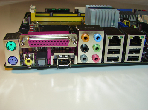
The Marvell 88SE6141 SATA II Raid ports, Intel USB connector, IEEE1394a connector, chassis panel, and Com1 serial port are located along the left edge of the board. The CMOS reset is a traditional jumper design located in-between the BIOS chip and the chassis panel.
We did not have any issues installing an ATI X850 Crossfire Edition setup in the two x16 PCI Express slots. This configuration will render the first PCI-X slot useless. There were not any issues utilizing this slot with video cards containing single slot cooling systems when utilizing our Areca ARC-1110 SATA II RAID host adapter.
One of the main design features that Asus engineered into this board is an exclusive 8-phase voltage regulator power design that can significantly lower operating temperatures while reducing input ripple current and output ripple voltages . In fact, the input ripple current is over three times lower than a traditional 4-phase design while output ripple voltages are four times lower. The power consumption compared to the 4-phase design is about 10% less while the 8-phase design has the advantage of quicker transient responses and increased dependability due to lower thermal values.
The Northbridge, Southbridge, and PCI-X chipsets are passively cooled with heatsinks that do not interfere with any installed peripherals. In fact, this system kept the chipsets cool enough that additional chipset voltage was not a factor in our overclocking tests. Asus places the eight-pin 12V auxiliary power connector at the top of the CPU socket area, but out of the way of most aftermarket cooling solutions.
The BIOS options are abundant on the Asus P5WDG2-WS, with memory voltage to 2.3V, and an extensive range of chipset, bus, and vCore voltage adjustments. Memory ratios are limited compared to the nForce4 Intel Edition boards, but Asus did manage to offer enough settings to make the board competitive. The board fully supports manual memory timing adjustments or allows for an Auto setting that will set the memory to the SPD settings. You have the ability to overclock the system utilizing the AI Overclock profiles that have preset percentages or to use the AI N.O.S. feature that will dynamically overclock the system based upon system loads.
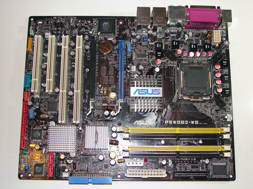
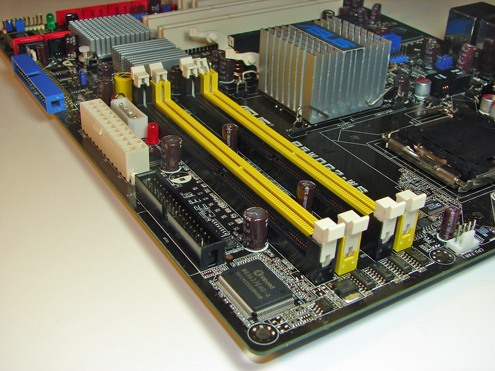
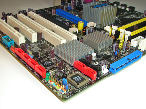
The Intel SATA II ports are conveniently located below the ICH7R chipset and above the primary IDE connector. The SATA II ports feature the new clamp and latch design. Asus did not include the new cable designs in their accessory kit, which greatly enhance the security of the SATA connections. However, the Intel SATA II ports are color coded for primary (Red) and secondary (Black) operation when the ports are set to Standard IDE mode.
The Intel 6702PXH chipset is located in between the DIMM module slots and ICH7R chipset. Below the 6702PXH chipset is a 6-pin jumper switch that allows you to set the PCI-X speed settings to Auto, Force 133MHz, and Force 100MHz.
The Marvell 88SE6141 SATA II Raid ports, Intel USB connector, IEEE1394a connector, chassis panel, and Com1 serial port are located along the left edge of the board. The CMOS reset is a traditional jumper design located in-between the BIOS chip and the chassis panel.
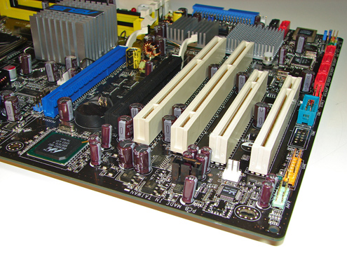
We did not have any issues installing an ATI X850 Crossfire Edition setup in the two x16 PCI Express slots. This configuration will render the first PCI-X slot useless. There were not any issues utilizing this slot with video cards containing single slot cooling systems when utilizing our Areca ARC-1110 SATA II RAID host adapter.
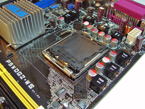
One of the main design features that Asus engineered into this board is an exclusive 8-phase voltage regulator power design that can significantly lower operating temperatures while reducing input ripple current and output ripple voltages . In fact, the input ripple current is over three times lower than a traditional 4-phase design while output ripple voltages are four times lower. The power consumption compared to the 4-phase design is about 10% less while the 8-phase design has the advantage of quicker transient responses and increased dependability due to lower thermal values.
The Northbridge, Southbridge, and PCI-X chipsets are passively cooled with heatsinks that do not interfere with any installed peripherals. In fact, this system kept the chipsets cool enough that additional chipset voltage was not a factor in our overclocking tests. Asus places the eight-pin 12V auxiliary power connector at the top of the CPU socket area, but out of the way of most aftermarket cooling solutions.
The BIOS options are abundant on the Asus P5WDG2-WS, with memory voltage to 2.3V, and an extensive range of chipset, bus, and vCore voltage adjustments. Memory ratios are limited compared to the nForce4 Intel Edition boards, but Asus did manage to offer enough settings to make the board competitive. The board fully supports manual memory timing adjustments or allows for an Auto setting that will set the memory to the SPD settings. You have the ability to overclock the system utilizing the AI Overclock profiles that have preset percentages or to use the AI N.O.S. feature that will dynamically overclock the system based upon system loads.


31 Comments
View All Comments
Cygni - Wednesday, December 7, 2005 - link
Workstation /= server...Overclocking isnt wacky in the worstation world at all. Picture a guy using 3dsmax everyday in his personal studio, or rendering TV streams in Maya, or doing texture work, or compiling source codes at a game studio...
Overclocking in the Workstation market is probably ALOT more common than people would think. Take overclocking that Pressler. That big of an overclock could mean whole DAYS of extra time per year that the CPU would have otherwise been spending cranking away on rendering. Thats a serious gain.
I dont think many serious servers will find a board like this one in em, to boot. Its lacking alot of features that a serious server hosting lots of users would deffinitly feel the need for... like built in SCSI, multi cpu support, RAM support over 8gig/4slot, etc.
On the other hand, this is a near perfect workstation board. High clocked RAM support for both ECC and non ECC. Non buffered memory. Both SLI and Crossfire support at 8x/8x. Plenty of SATA II plugs for cheap storage.
I took notice of the OC results and settings, and i like what i saw. :)
Cygni - Wednesday, December 7, 2005 - link
That was a reply to the poster one level up, sorry. :DThanks for taking the time to do the OC tests, however. Some people out there did like to see em.
Zebo - Tuesday, December 6, 2005 - link
If those 4.8ghz air overclocks are normal intel won't have to wait for conroe to take back enthusiasts crown. That's amazing.Leper Messiah - Tuesday, December 6, 2005 - link
Hell yeah. 4.8GHz on air with Dual core is a 20% over what an 840EE will do. And I bet that with nF4 and a DFI 5.0+ is possible. oooh. Sexay.stephenbrooks - Tuesday, December 6, 2005 - link
Yeah, I'm wondering if the Pentium D 920 might become a new "favourite" chip for them to play with :)Niv KA - Tuesday, December 6, 2005 - link
Talking about Conroe, isn't the 975X supposed to support upgradability to itxtremejack - Tuesday, December 6, 2005 - link
If you look at the chipset price guides for this month by Anand, 975x will not support ConroeGary Key - Tuesday, December 6, 2005 - link
Intel has not officially confirmed either way on the 975X to Conroe path. We have heard both a positive and negative on this but from different sources. As soon as we have a clear path it will be posted.Niv KA - Tuesday, December 6, 2005 - link
That would mean I could buy a 975X based MB with a Celeron and buy a Conroe in the summer without having to buy a new motherbord and allCalin - Tuesday, December 6, 2005 - link
When the graphs shows both min framerate and max framerate, I suggest that ordering should be done by the min framerate instead of the max framerate. Only on F.E.A.R. Performance test on the 9th page the results will change, and only for the top two boards - however, I prefer to have good consistent high framerate in the worst cases than extremely high framerate in the best conditions.Thanks